YAESU FT-DX101D

Yaesu FT-DX101D HF/50MHz 100W SDR

Yaesu FT-DX101D HF/50MHz 100W SDR Reservation

YAESU is excited to introduce a new High-Class HF/50MHz 100WTransceiver – FTDX101D and the first sample will be seen at Dayton Hamvention 2018.

The new FTDX101D is utilizing the latest SDR Technology and classified as our High-End HF line, the FTDX series, which amateurs have come to know represents quality.

A few of the remarkable features of the new FTDX101D are;

  • YAESU High-Class HF/ 50MHz 100W Transceiver
  • SDR Technology and Waterfall Display
  • Large Touch Panel precision color display
  • Active Band Monitor enables rapid band changes with LED illumination of the operating band
  • Independent control of the Main and Sub Bands allows effortless operation for the serious contester needing to move quickly between the amateur bands
  • High-Q VC Tuning Front-End
  • Main tuning dial for Main and Sub Band frequency control includes an Outer Dial for clarifier, VC tuning, fine tuning or custom settings.

As you may recall, the name “101” comes from Yaesu’s legendary-popular best seller FT-101 series. With all its strength, YAESU produced this new HF transceiver to carry on the tradition of high quality known from the original 101 series. The new FTDX101D will be certain to satisfy the variety of many amateur radio enthusiasts’ demands.

Sdr versatile tutta da scoprire

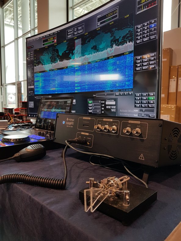
HAMLAB RED PITAYA


Red Pitaya è la ben nota piattaforma open source basata sul sistema operativo GNU/Linux, di dimensioni estremamente compatte e dotata di processore dual core ARM Cortex A9, FPGA, DDR3 RAM 512 MB, ingressi analogici, uscite analogiche, I/O digitali, porta Ethernet, slot per memorie micro SD card e via discorrendo. Red Pitaya può fare un sacco di cose ma HAMLAB ne amplia i modi di funzionamento. Con HAMLAB si può combinare la magia di una Software Defined Radio con una serie di indispensabili strumenti da laboratorio. HAMLAB è infatti SDR, oscilloscopio, spectrum analyzer, logic analyzer, network vector analyzer e molto altro. In modalità oscilloscopio dispone di due canali di ingresso con banda di 50 MHz, sampling rate di 125 Msps, input range di ± 20 volt, risoluzione di 14 bit. In modalità spectrum analyzer dispone di due canali di ingresso con banda di 62 MHz, range dinamico di -80 dBm e input noise level di -119 dBm/Hz. In modalità logic analyzer dispone di otto canali di ingresso, sampling rate di 125 Msps, livelli logici 2,5/3,3/5 volt, con decodifica dei protocolli SPI, UART, I2C. Ma di gran lunga più interessante per il mondo radioamatoriale è la modalità SDR. Copertura di frequenza in trasmissione da 1 MHz fino a 62 MHz, quindi tutte le bande 160/80/40/30/20/17/15/12/10/6 metri. Potenza di uscita TX 10 watt con stadio finale LDMOSFET. Per chi vuole “esagerare” è disponibile una versione con uscita di 100 watt. Copertura di frequenza in ricezione da 25 kHz fino a 62,25 MHz. Architettura del ricevitore direct sampling con possibilità di attivare un secondo ricevitore. Preamplificatori da 15/30 dB e attenuatori da 12/24/36 dB incorporati. Connessione diretta per un tasto morse o per un microfono con PTT. Due ingressi di antenna selezionabili via software con connettori BNC e SO-239 UHF. Disponibili come option un preselettore e un controllore con “manopolona” che semplifica le impostazioni delle differenti modalità di funzionamento del RTX. Alimentazione richiesta 12 volt 4 ampere (che salgono a 10 ampere per la versione con 100 watt output). I software supportati sono PowerSDR, HDSDR, Gqrx, GNU Radio, GNU Radio Companion e Pothos. Un laboratorio elettronico di alto livello e un RTX di alte prestazioni racchiusi in uno spazio estremamente ridotto per venire incontro a tutte le esigenze di una moderna stazione radioamatoriale. Con HAMLAB si può fare veramente di tutto. Non a caso lo slogan pubblicitario scelto per HAMLAB è “Swiss army knife for HAM radio operators”. Maggiori informazioni su http://hamlab.redpitaya.com/

Nuovo modo digitale FT8 da K1JT

Eh si, il mondo della radio è sempre in evoluzione. 

Il noto radioamatore americano K1JT  ha rilasciato un nuovo modo di trasmissione digitale chiamato FT8, per ora integrato nel programma di codifica e decodifica WSJT-X in versione beta dalla release numero 1.8.0-rc1-

Come dice la pagina di WSJT-X, questo programma  implementa molti protocolli di comunicazione o “modi”:

JT4 , JT9 , JT65 , QRA64 , ISCAT , MSK144 e WSPR , così come quella denominata Echo per rilevare e misurare i propri segnali radio riflessi dalla Luna.

Queste modalità di trasmissione  sono stati progettati per rendere affidabile e  confermare  QSO con  segnali estremamente deboli.  Video dimostrativo


Icom IC-7300 New! – Toyko HamFair 2015

IC-7300 that Icom has been announced, in SSB / CW / RTTY / AM / FM transceiver of HF ~ 50MHz band, “IC-7300″ of 100W output, “IC-7300M” of 50W type, of 10W type “IC- 7300S “me to line up. Features are as follows.
– It is equipped with a high-performance real-time scope equipped with a practical skills
Amateur radio’s first adopted the “RF direct sampling method”
(as the main amateur radio equipment manufacturer)

The implementation phase noise characteristics that transcend the class
Equipped with a large color TFT LCD display that corresponds to the touch panel
– In a compact body, and a built-in antenna tuner
– Audible high sound quality is achieved.

FB_IMG_1440437510112

FB_IMG_1440437466280

FB_IMG_1440437482500

IC-7300_icom

11038007_914805078593726_7208670379565171804_n

FB_IMG_1440217110234

Professor Hidetsugu Yagi. 1886 – 1976.

hyagi

Professor Hidetsugu Yagi was born in year 19 of the Meiji Era (January 28 1886 to you and I) in Osaka prefecture, Japan. I have been unable to discover anything about his early life but he graduated in engineering from Tokyo Imperial University in 1909.

After graduating he went to Germany, where he continued his education under the direction of Heinricti Barkhausen, inventor of the Barkhausen oscillator.

Yagi’s research in Germany concerned resonant transformers used in wireless systems. The outbreak of the First World War forced his hurried departure, leaving all his experimental data behind. He later published a paper on the theoretical part of this research in the December 1917 Proceedings of the Institute of Radio Engineers.

Yagi had fled Germany to Great Britain where he studied with John A. Fleming until 1916. Before returning to Japan, Yagi visited the United States and spent some time at Harvard University with George W. Pierce. Yagi then began his teaching career at Tohoku Imperial University, which awarded him a doctorate in engineering in 1919.

At Tohoku University, Yagi initiated a research program in radio-electronics, drawing on the knowledge that he had learned with Barkhausen, Fleming, and Pierce. Other members of the faculty and advanced students, including Okabe and Shintaro Uda, became participants in a collective research effort.

A perceived need for better communication between islands and with ships led them to focus on short wave communication with directive antennas. The Yagi group received financial support for the research from a private foundation in Sendai.

In 1925 Yagi and Uda published their first report on the wave projector antenna in a Japanese publication. In the paper, they discussed the design and performance of a directive antenna that they called a “wave projector” or “wave canal” and which had been developed at the University.

The antenna employed a number of parasitic elements called directors and reflectors and would come to be known as the Yagi antenna or (as it should properly be called) Yagi-Uda antenna.

Yagi applied for patents on the new antenna both in Japan and the United States. His Japanese patent was issued in 1925 and the U.S. patent was issued in 1932 and assigned to the Radio Corporation of America.

Yagi made another visit to the United States in 1928 and gave talks on the Japanese short wave research at Institute of Radio Engineers meetings in several cities and for a group of engineers at General Electric.

His visit stimulated a renewed interest in magnetrons at GE and they developed a 400-MHz magnetron and tested it with a wave projector during the summer of 1928.

The Bureau of Standards engineers also used a Yagi-Uda antenna in an experimental aircraft landing system in 1930.

In 1933 Yagi moved to Osaka Imperial University, the newest and the last Imperial University established with the support from the industry rather than the government, as the 1st chair of the physics department in the faculty of science, the director of a laboratory where developmental work on radar took place. Yagi promoted pure science and encouraged the younger professors and researchers to pursue fundamental physics rather than applied physics while doing the applied part himself to fulfil the industry’s needs. Also that year the short-wave system developed at Tohoku University was used to establish a government radio telephone link between Sakata and Tobishima Island, a distance of about 40 km.

In 1939 he was made Dean of the Faculty of Science at the Osaka Imperial University. In 1944 he became President of the Technology Institute of the Cabinet.

Yagi served as a Civilian Consultant on radar and communication to the Japanese military during World War II. Unfortunately his home, library and most of his personal papers were lost during a bombing raid in April 1945.

Soon after the end of the war he was interviewed by Roger I. Wilkinson, William R. Hewlett and others concerning Japanese developments during the war. In these interviews Yagi expressed frustration over the poor communication and cooperation between the military services and civilian experts.

Gentai Sato, who studied under Yagi, wrote about the surprise to the Japanese when they captured British radar systems equipped with Yagi antennas and a document on Yagi arrays found when Singapore was taken. Sato also noted the irony of the American use of Yagi antennas to determine the height of the explosion of the atomic bombs dropped on Japan.

After the war Yagi served as a consultant on the technological rehabilitation of Japan and assisted in the formulation of television standards. In 1946 he was installed as the 4th President of Osaka Imperial University, and was also President of Japan Amateur Radio League (JARL). He also served as president of the Yagi Antenna Company and was awarded Japan’s Order of Cultural Merit in 1956. He died on January 19 1976, just 9 days short of his 90th birthday.

Yagi was an excellent manager and producer of science, though his methods were, sometimes, unorthodox. It is reported that Professor Yagi had a sharp tongue and encouraged Dr. Hideki Yukawa in very special way with the bitter words “We originally planned to employ Dr. Shinnichiro Tomonaga. However since your elder brother begged us to employ you, we recruited you instead. Please do not make us disappointed. Work harder than Dr. Tomonaga”. Shortly afterwards Dr. Yukawa published his first paper which later brought him the 1st Nobel Prize in Japan. It is believed that the words of Professor Yagi urged Dr. Yukawa to publish his MESON theory although nobody knows what really happened between Professor Yagi and Dr. Yukawa.

When Shintaro Uda visited the United States in 1951 he expressed astonishment at the ubiquity of the Yagi-Uda antennas used as home television antennas.
hyagi


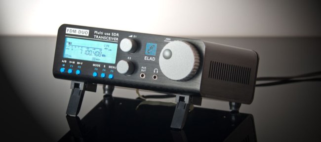
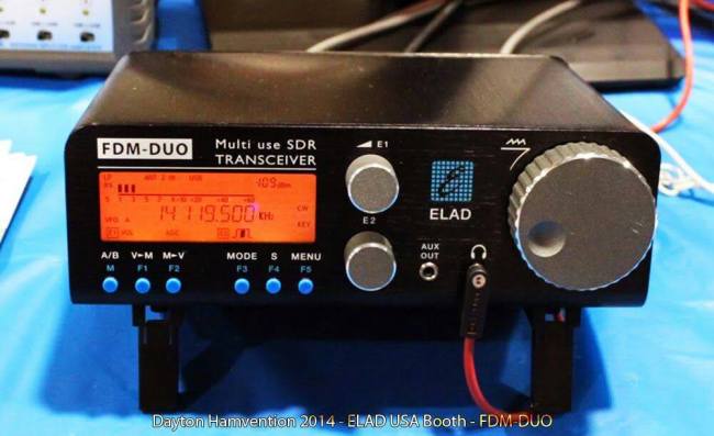
Elad FDM-DUO standalone SDR HF+6m transceiver Dayton Hamvention® 2014 Product Made in Italy

Things seem to be going the right way for SDR technology. The latest spawn from Italy – calledELAD FDM DUO – definetely got my interest; we are talking about a direct sampling full SDR transceiver for HF/6m, that can also run standalone. The closest thing to it might be the Elecraft KX-3, but that is considerably behind in technology and still manages to have one of the top recievers aroundImmagine.

The ELAD FDM-DUO recieves from 9KHz to 52MHz and covers all the amateur bands from 160m to 6m, claiming an MDS of -132dB and an BDR or +115dB @ 500Hz. Power output is only 5watt

Besides being standalone, it can also be attached to a computer so you can benefit from all the power of the SDR technology: big spectrum analizer (up to 6MHz), dual recievers, total control via their SW-2software etc.

Immagine


Here’s what makes it go:
– ADC: Linear Technology LTC2165 clocked at 122.88MHz
– DDC: Xilinx Spartan 6 XC6SLX25 FPGA + serial flash
– DDS: AD9957
– 2x STM32F4 microcontrollers


What I don’t like about it is the fact that it is not concieved as a product, but looks more as a technological demo, made entirely by engineers. The hefty pricetag (1160EUR, about US$ 1600) asks for a good user interface, useful output power and decent build quality, otherwise it will be just a stillborn novelty – interesting from a technological standpoint but not appealing to purchase and use. FDM-DUO’s kickass electronics with 100W output and a useful front panel could definetely your main station transceiver. 

APRSdroid is an APRS application for Amateur Radio

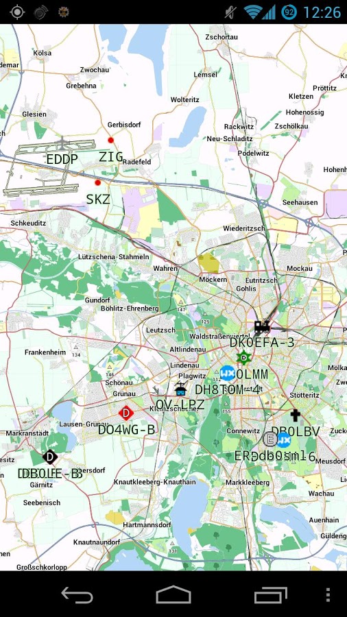
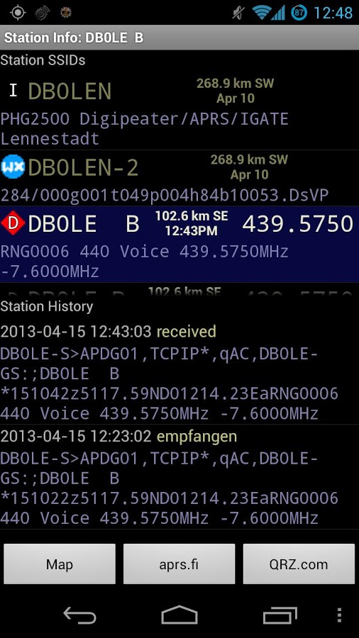
APRSdroid is an Android application for Amateur Radio operators. It allows reporting your position to the APRS (Automatic Packet Reporting System) network, displaying of nearby amateur radio stations and the exchange of APRS messages.

APRSdroid is Open Source Software written in Scala and licensed under the GPLv2.    

The APRSdroid features are:
* See what is going on on APRS with the Hub View or on the map
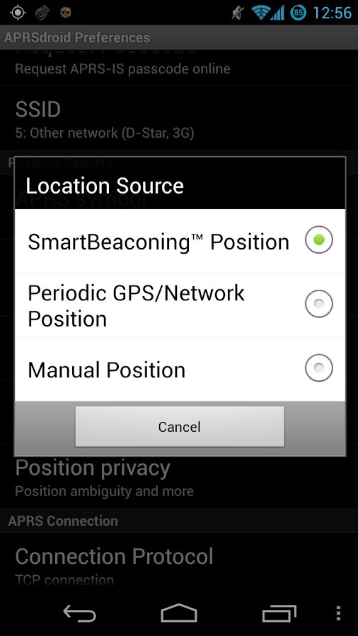
* One-time or periodic position reporting to APRS
* APRS Messaging support
* Get detailed information about a station
* Follow the movement of a station on the map
* Support for GPS and network location
* Bi-directional APRS-IS support via TCP and AFSK
* Unidirectional position reporting via UDP and HTTP    unnamedggg  
artrtr unnamedytyr  Watch the video

youtube_logo

DroidRTTY is an application to decode and encode RTTY

DroidRTTY is an application to decode and encode Ham Radio RTTY with the build in microphone/speaker or wired to your radio.

A waterfall shows the frequency spectrum of 100Hz to 2500Hz. Just slide the waterfall slide on a RTTY carrier frequency and DroidRTTY will decode the signal.

In transmitting mode characters can be entered trough the keyboard. 9 Macros are also available to store standard texts like “name and qth” and “station info”

DroidRTTY also now includes a logbook. Callsign, Name RST etc can be easily tranfered into the lookbook from the receiving screen.
The logbook also includes ADIF export and import to transfer your logbook data to a PC based logging software.


DroidRTTY è un’applicazione per decodificare e codificare RTTY

Una cascata mostra lo spettro di frequenza di 100Hz a 2500Hz. Basta far scorrere il vetrino cascata su una frequenza portante RTTY e DroidRTTY decodifica il segnale.

Nel trasmettere in modalità caratteri possono essere inseriti attraverso la tastiera.  Le macro sono disponibili anche per memorizzare testi standard come “nome e QTH” e “info stazione”

DroidRTTY ora include anche un diario di bordo. Nominativo, nome ecc RST possono essere facilmente tranfered nel lookbook dalla schermata di ricezione.
Il registro comprende anche l’esportazione e l’importazione ADIF per trasferire i dati del giornale di un software per PC di registrazione.

unnamedee

unnamedffg

unnamedggg

Watch the video

youtube_logo


DroidPSK is an application to decode and encode Ham Radio BPSK31

DroidPSK is an application to decode and encode Ham Radio BPSK31. A great tool for portable Amateur Radio PSK operation.
DroidPSK is able to decode a BPSK31 signal though the build in microphone. Just hold your Android phone or tablet close to the speaker of you Amateur Radio transceiver, adjust the waterfall slider to the PSK carrier frequencies and DroidPSK will start decoding.
In transmitting mode characters can be entered trough the keyboard. 9 Macros are also available to store standard texts like “name and qth” and “station info”
Starting V2.0 DroidPSK now also includes a logbook. Callsign, Name RST etc can be easily transferred into the lookbook from the receiving screen. The logbook also includes ADIF export and import to transfer your logbook data to a PC based logging software.

DroidPSK è un programma per decodificare segnali digitali come  BPSK31. Un ottimo strumento per radioamatori
DroidPSK è in grado di decodificare un segnale BPSK31  Basta tenere il vostro telefono Android o tablet vicino al ricetrasmettitore radioamatoriale, regolare il cursore cascata per le frequenze portanti PSK e DroidPSK inizierà la decodifica.

unnamedddd

unnamedss

unnamed

Watch the videoyoutube_logo

DroidSSTV lets you transmit and receive amateur radio on your Android Smartphone

DroidSSTV lets you transmit and receive amateur radio (ham radio) slow scan TV (SSTV) on your Android Smartphone or Android tablet. This communications app is a great tool for portable amateur radio SSTV operation. Just connect your Android phone or tablet to an HF radio (or even set it next to the radio’s speaker), tune on to an SSTV frequency, and watch the pictures scroll onto the screen. DroidSSTV supports the ham radio modes Scottie 1, Scottie 2, Scottie DX, Martin 1, and Martin 2 at this time.

The features in the receiving modes include:

– Spectrum analyzer for easy tuning
– Auto synchronization ( auto slant correction)
– Auto mode detect
– VIS encoding (detects SSTV header and sets mode automatically)
– Level bar for adjusting the audio signal
– Auto save received pictures to SD Card.
– Share received pictures (Email , Dropbox etc.)
The features in the transmitting modes include:

– Pre-load up to 9 pictures from the SD Card into DroidSSTV’s gallery
– Adjust contrast, brightness and saturation
– Template editor for easily overlaying templates over images
– Macro’s for use with templates

unnamed

DroidSSTV consente di trasmettere e ricevere radioamatori (radioamatori) slow scan TV (SSTV) sul vostro smartphone Android o tablet Android. Questa applicazione di comunicazione è un ottimo strumento per il funzionamento radio portatile amatoriale SSTV. Basta collegare il telefono o tablet Android a una radio HF (o anche impostare accanto alla speaker della radio), sintonizzarsi su una frequenza SSTV, e guardare le immagini scorrere sullo schermo. DroidSSTV supporta le modalità di radioamatori Scottie 1, Scottie 2, Scottie DX, Martin 1, e Martin 2.

   Watch the video     youtube_logo